
Skip to content
Wattality

Product family

The decision and control layer of energy infrastructure.

Measurement flows up, decisions flow down. We are developing the product family on a common architecture that connects cell measurement to facility and fleet decisions.

01 / 06Cell level

Sense

Cell-level measurement

Sense · cell-level measurement
Schematic
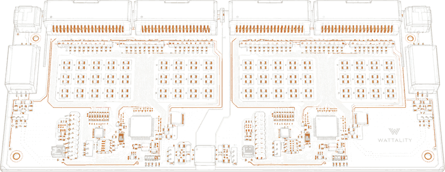
Line drawing of the Sense measurement board: cell connectors along the top edge, rows of measurement channels, two processors and isolated communication connectors at both ends.

Measurement board, front view · not to scale

Battery insight starts at the cell.

Voltage and temperature monitor the cell from the outside. Electrochemical impedance spectroscopy (EIS) measures internal resistance and chemical change.

Sense is being developed to assess signs of aging, imbalance and faults through cell-level measurement.

We are developing measurement electronics and diagnostic models together to make data on a cell's internal resistance and chemical state observable while the system operates.

Scale
Cell level
Role
Cell-level measurement
For
Battery and storage system owners; acceptance testing is also an intended use.
02 / 06Pack and container

Core

Pack, rack and container control

Core · pack, rack and container control
Schematic
12378456
  1. 1Core container controller · decides for every rack
  2. 2Rack controller · one on every rack
  3. 3Measurement up · pack → rack → container
  4. 4Decisions down · container → rack → pack
  5. 5Measurement board · on every pack
  6. 6Battery racks · packs stacked in every rack
  7. 7Protection and switching · at the foot of every rack
  8. 8Container · front wall removed

Cutaway, front wall removed · not to scale

Energy transfer between packs.

Core is designed to manage energy transfer as well as pack protection and balancing. The aim is to reduce how much differences between packs limit usable container capacity.

An isolated bidirectional converter forms the hardware layer for moving energy between packs.

Scale
Pack and container
Role
Pack, rack and container control
For
Container and system integrators.
03 / 06Pack and container

DC/DC

Bidirectional DC/DC converter · pack balancing

DC/DC · pack balancing
Schematic
1234567891011
  1. 1Rack
  2. 2Battery pack (module)
  3. 3Weaker pack · found by measurement
  4. 4DC/DC module inside every pack · isolated, bidirectional
  5. 5Shared balancing bus · DC+ · DC−
  6. 6Power switches · one bridge per side
  7. 7Isolation transformer · across the barrier
  8. 8Heatsink
  9. 9Filter capacitors
  10. 10Pack side
  11. 11Current and voltage · sensing

Front view of two racks and detail A · not to scale

The hardware Core moves energy through.

In the design, each pack connects to a shared balancing bus through an isolated bidirectional converter. Core sets the direction and current of energy transfer.

Scale
Pack and container
Role
Bidirectional DC/DC converter · pack balancing
For
Container and system integrators, alongside Core.
04 / 06Server rack

BBU

Server rack backup power

BBU · in-rack backup
Schematic
123456
  1. 1Network switch · and patch panel
  2. 2IT load · servers
  3. 3BBU shelves · backup power inside the rack
  4. 4DC busbar · runs the height of the rack
  5. 5IT load · servers
  6. 6Perforated front door

Oblique view, side panel removed · not to scale

The same architecture, at the server rack.

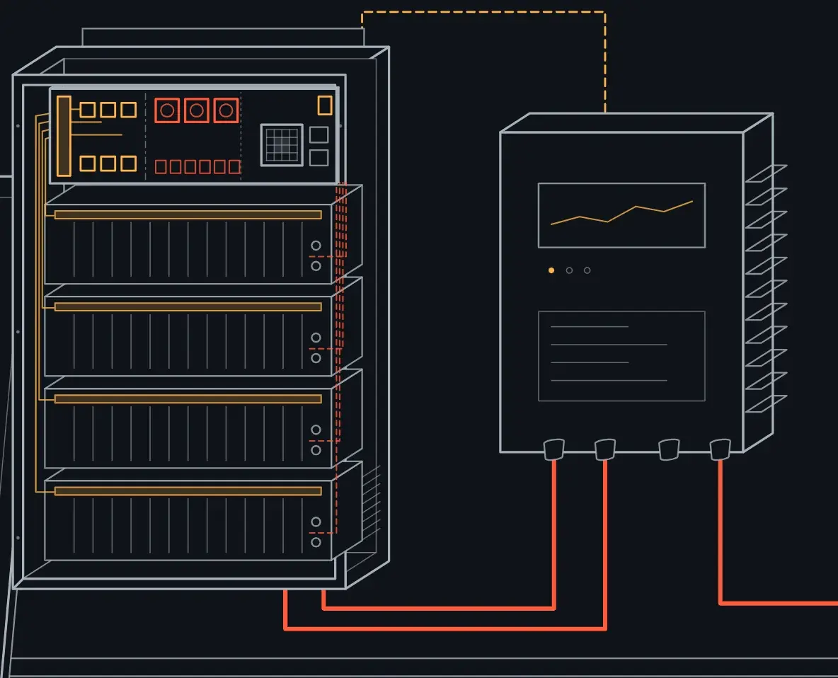
BBU is a backup-power design for the server rack's power line. Cell measurement, pack control and response to rapid load changes are considered within the same architecture.

Scale
Server rack
Role
Server rack backup power
For
Data center operators and server makers.
Applications
AI data centers
05 / 06Facility level

Site

Single point of control for facility and site

Site · the facility as one system
Schematic
12348910567
  1. 1Site controller · on site, decides for the facility
  2. 2Solar field · panels and inverter
  3. 3Battery storage · Sense and Core inside
  4. 4Generator · standby supply
  5. 5Grid connection · line and transformer
  6. 6Grid breaker · open: islanded operation · closed: reconnected
  7. 7Facility loads · IT halls and cooling
  8. 8AI models run on site · inside the controller
  9. 9Measurement · every source → controller
  10. 10Decisions and dispatch · controller → every source

Oblique view · not to scale

Treating the facility as one system.

Site is being developed to coordinate the battery, power converter, grid connection, generation and facility loads together.

Islanded operation during a grid outage and reconnection afterwards are among its intended control capabilities.

Keeping control on site without dependence on a cloud connection is a core architectural principle.

Scale
Facility level
Role
Single point of control for facility and site
For
Data center operators and storage asset owners.
06 / 06Fleet level

Fleet

The layer that manages the value of the fleet

Fleet · every site in one view
Schematic
1234567891011
  1. 1Fleet, in the cloud · one view across sites
  2. 2Remaining life · per asset
  3. 3Risk · fault probability
  4. 4Value · performance and revenue
  5. 5Model development · on data from every site
  6. 6Site data · every site → Fleet
  7. 7Models · Fleet → every site
  8. 8Site controller · decisions stay on site
  9. 9AI data center · IT hall and battery storage
  10. 10Critical facility · battery and generator
  11. 11Grid-scale storage · containers and power conversion

Oblique view · not to scale

Technical performance and economic value, together.

Fleet is designed to bring technical and commercial data from sites into one view. The aim is to see performance differences alongside their technical causes.

We are developing fleet-level models for remaining life, fault probability and revenue forecasts. Validation and updates using field data are planned as those data become available.

Value and Forecast Engine

Scale
Fleet level
Role
The layer that manages the value of the fleet
For
Asset owners and financiers.

A planned product.

Deliverable Energy Guarantee

A planned approach to estimating deliverable energy from battery condition and carrying that estimate into operating limits.

Measurement-based limits are intended to inform facility control.

Product family

Ways to work together

  1. 01

    Own products

    Maturing technology components reach the market under our own product families. Hardware, embedded software and higher-level software are developed as parts of one product strategy.

  2. 02

    Design-in and licensing

    Our technology components can be designed into manufacturers' own products.

  3. 03

    Integrated systems

    For strategic projects, we aim to develop integrated energy and critical power systems carrying Wattality technology.

  4. 04

    Lifecycle services

    Planned service areas: software updates, performance analysis, remote monitoring and optimization.

The same battery knowledge, on other platforms.

We aim to carry the measurement, balancing and embedded-AI approach we develop for critical power into battery systems at other scales.

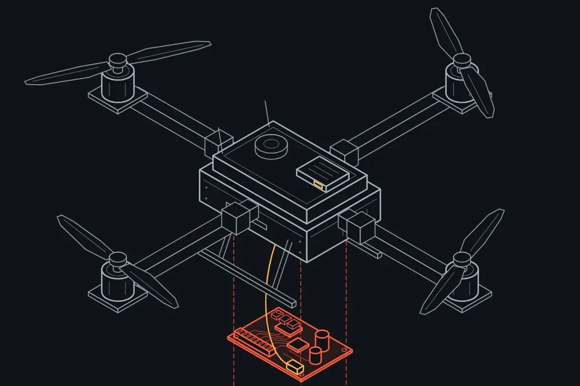
Intelligent battery management for drone and UAV platforms

The platform that tracks the energy of flight.

We aim to build a platform that tracks battery state and energy use and provides battery data to flight control systems. The design covers integration with different drone and battery manufacturers.
Home energy storage

The safety, performance and life of the battery at home, on one platform.

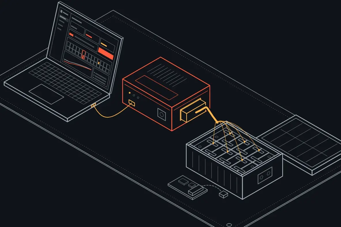
The home-storage design brings Sense's cell measurement, Core's balancing approach and embedded models together on one board.

Drone battery repairThe workstation that makes drone batteries repairable.Dengera is a device-and-interface package that measures agricultural drone batteries cell by cell, balances them and records every repair. We built it for repair workshops.Explore Dengera

Let's discuss our products.

Write to us about our technology and your application needs.