How a GPU training load affects generators and the UPS
In AI training, the power of thousands of GPUs falls and rises at the same moment. Where that change shows up on the grid, the generator and the UPS, and what to check in design.
- Published
- Updated
- 7 min read
- 7 min read

The utility has gone down, and the facility's generators are now feeding an AI training hall. Thousands of GPUs in the hall are working on one model. In every training step they all compute at the same time, then all wait at the same time to exchange results. The hall's total power falls and rises with those steps.
The electrical design usually models this load as a constant kW figure. That figure can get the average right, but it does not show how the load changes over a few seconds. While the facility is on the grid, the point of connection sees that change. Once the facility separates from the grid, the generators' speed and voltage control has to absorb it directly.
Why a training load makes the hall's total power swing
In a conventional data center, the hall load is the sum of thousands of servers working independently. Each server's load fluctuates, but across the hall those fluctuations largely even out. The total changes slowly.
In a training job, the GPUs work together and wait for each other at the end of every step. GPU power is high in the compute phase and drops in the communication phase. Because every GPU enters those phases at the same moment, the fluctuations add up. The load has a few familiar shapes:
- When the job starts, the GPUs go from idle to full load in a short time (the start-up ramp).
- Compute and communication phases alternate, and the hall load steps down and up with them.
- At intervals the job pauses to save its state. GPU power falls toward idle during the save and climbs back when it ends (a checkpoint).
- Training steps repeat at regular intervals, so the load can oscillate at a frequency tied to the step time.
- When the job ends or stops on an error, the load drops at once.
Where the swing shows up while on the grid
While the facility runs on the grid, every change in load also appears at the point of connection. On a strong grid, frequency barely moves. Voltage, however, moves with the load across the impedance of the line and the transformer.
Grid operators track that movement against power-quality limits. Fast, repeated voltage changes show up for other customers on the same line as flicker, a visible flutter in their lighting. A large, fast-changing load can face ramp-rate and oscillation conditions in its interconnection application. Repeated oscillation at certain frequencies can also interact with the control and mechanical systems of nearby generating plants.
A facility that presents a smooth power profile at the point of connection meets those conditions more easily.
How a generator responds to load changes in island mode
Island mode means the facility has separated from the grid and runs on its own generators. A generator has two control loops. The governor holds engine speed, and with it frequency. The automatic voltage regulator (AVR) holds output voltage. Both respond to a load change at a limited rate.
When load is added (load acceptance), the engine slows until it can raise fuel and torque, and frequency falls. At the same moment the drop across the alternator's internal impedance grows and voltage dips. The regulators bring both back, but that takes time. Generator manufacturers establish this behavior with stepped load tests under ISO 8528-5. At each step, the frequency and voltage dips and the recovery times have to stay within limits. Gas engines usually accept smaller steps than diesel engines.
When load is removed (load rejection), the reverse happens. The engine speeds up, and frequency and voltage rise. A large load rejection can be hard enough to trip the overspeed protection.
When load oscillates, the two cases repeat one after the other. If the oscillation is close to the governor's response time, the governor keeps correcting, and the frequency swing can grow instead of dying out. Load sharing between generators running in parallel is affected too.
With example values: four 2 MW generators feed a hall drawing 6 MW. During a checkpoint the load falls to 3 MW. Each generator drops from 1.5 MW to 0.75 MW, and when the save ends the same 0.75 MW step comes back. That is a load acceptance step of 37.5% of each generator's rating. Whether a generator can take a step that size in one go should be checked against the manufacturer's load acceptance test data.
A training job's start-up ramp is one large load acceptance step. A checkpoint is a load rejection, and its end is a new acceptance step. The repeating step-to-step oscillation is the kind of load regulators find hardest to follow. For island mode, a static load flow is therefore not enough. It takes a dynamic study that uses real models of the generator and its regulators.
The UPS topology decides whether the swing reaches the source
Between the grid or generator and the servers sits the UPS. How the UPS is built largely decides whether the load swing reaches the source.
In a double-conversion UPS, the load is always fed from the inverter. The rectifier draws from the source whatever the load needs, so as it follows the load, the swing passes to the source. Many double-conversion UPSs can limit the rise in input power with a ramp and cover the difference briefly from the battery (input current walk-in). That setting is designed mainly for the moment of transfer to generator. How much it helps with a repeating training load depends on the UPS control settings and on whether the battery can handle that cycling.
In a line-interactive UPS, the load is fed directly from the source while the source is within tolerance. The inverter steps in only when the source leaves that tolerance. In this arrangement the load swing passes straight to the source, and in island mode to the generator.
Every arrangement that smooths the swing does so by putting the battery through some cycling. That is why a UPS battery should be tracked for the work it does every day, not only for outages. We explain how its real power capability can be tracked in this post.
Which layer covers which time scale
No single piece of equipment covers every time scale of a training load. Splitting the response into layers by time scale makes the design sturdier.
- Rack level, milliseconds to seconds. The battery backup unit (BBU) in the server rack sits closest to the GPU. If it meets the fastest steps inside the rack, a slower change is left for everything upstream.
- Facility battery, seconds to minutes. Longer changes, such as checkpoint dips, job starts and the transfer to generator, are carried by the facility battery.
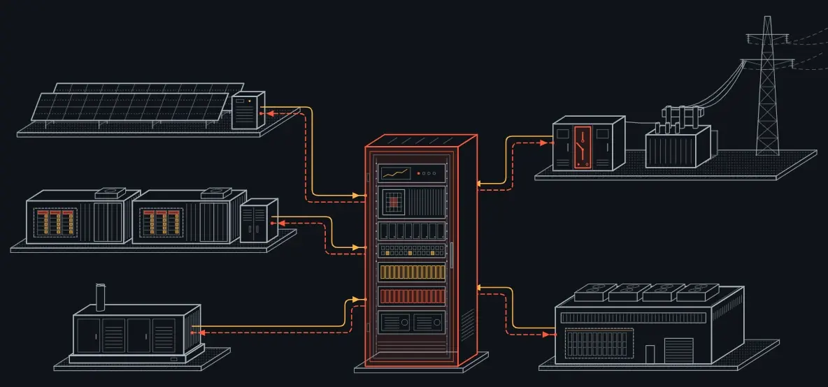
- Supervisory control, coordinating the sources. A facility controller runs the grid, the generators, the UPS and the batteries as one system. It decides which source meets which change, sets the ramp limits and determines when the generators need to be ready.
Supervisory control stays outside the protection chain. Protection relays and the UPS's own controls keep working fast and on their own. The supervisor manages setpoints and operating modes and takes no part in a trip decision. If something goes wrong in the control layer, protection keeps working.
What to check in design, and what to ask your vendors
- Ask for the load as a time series. Ask the IT team for the step time, the checkpoint interval and duration, and GPU power at idle and at full load. Design with that profile instead of a constant kW.
- Ask for the generator's load acceptance data. Ask for the ISO 8528-5 performance class, the load steps used in testing, and the frequency and voltage dip at each step. Ask how the governor behaves under repeating load changes.
- Ask how the UPS works with the generator. Ask for the adjustment range of the input walk-in, and how much of the load swing the battery can cover while running on generator. For a line-interactive UPS, find out how the swing passes to the input.
- Study island mode dynamically. Put the generator, its governor and voltage regulator, and the UPS into the same simulation with their real models.
- Reproduce the load at commissioning. Use programmable load banks to apply the steps and the oscillation. Record generator frequency and voltage, and UPS battery current.
What Wattality is developing across these layers
Wattality is developing this layered response in one architecture. BBU is designed to respond to fast load changes on the server rack's power line. Site is being developed to coordinate the grid, generators and batteries as one system while staying outside the protection chain. Sense and Core aim to bring the battery's real capability at that moment into those decisions.
We show the chain from the grid to the server rack, and where each product sits in it, in the power distribution section of our AI data centers page.
- AI data center
- Generator
- Load swings
- UPS
- BBU
- Facility control